
Posted on May 15, 2005
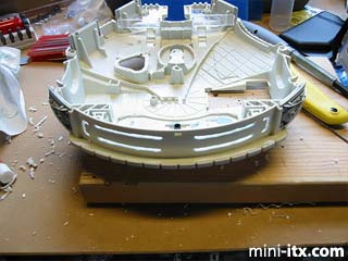
One of the goals of the project was to make the engine lite up. The toy came with stickers for the engine design, but that wasn't enough. I bought some EL wire and cut some grooves in the back to run the wire through. The one I got was pretty long so I wound up running it throughout the case as well, securing it with a hot glue gun.
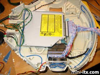
So now it was time to start putting the computer together. You can see here the hard drive mounted under the DVD platform. In this picture I used round IDE cables and had stripped off the casing believing it would be easier to route just the thin wires, but it turned out being a pain and I wound up using regular round cables as you'll see at the end. You can also see the cooling fan mounted at the side (right over the power switch) and some LEDs mounted in the front which were going to be for power/hdd etc. I also wound up changing this as you'll see.
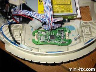
The main use for this computer was going to be as a multimedia PC hooked up to the TV. The mini-itx board already has TV out, but I wanted a TV-in as well. I bought a small USB based video converter and stripped off the case. You can see the board for it here. Unfortunately the VIA board doesn't seem to be fast enough to handle the video input and the input is pretty useless.
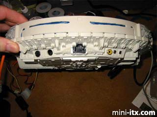
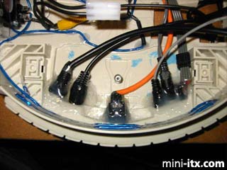
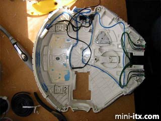
Next were the I/O connectors. They are mounted in the back and provide S-Video in and out, audio in and out, SPDIF out, and ethernet. I had never really known the wonders of hot glue until I worked on this project, but you can see it was used liberally. The connectors came from Frontx and had to be whittled down and spliced shorter. I think this was another place for improvement and I should have made my own connectors. One nice thing about the Front connectors was that they have direct motherboard connectors so you can save some space that way.
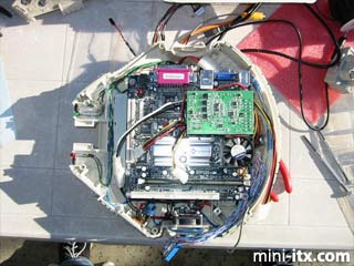
In this picture, you can see the motherboard stacked up on the drives. Near the bottom, you can see the transformer for the EL wire (left of the fan) and the switch to turn it on (just to the right of the fan). You can also see a change in the LEDs at the front. I changed it to have just two LEDS (green power & red HDD), but added an IR interface. The black blob near the green LED is a LIRC compatible IR receiver. The black blob at the bottom is another one, but is hooked up to nothing and is just there to give a symmetrical look.
 |
 |
 |
Quick Links
Mailing Lists:
Mini-ITX Store
Projects:
Show Random
Accordion-ITX
Aircraft Carrier
Ambulator 1
AMD Case
Ammo Box
Ammo Tux
AmmoLAN
amPC
Animal SNES
Atari 800 ITX
Attache Server
Aunt Hagar's Mini-ITX
Bantam PC
BBC ITX B
Bender PC
Biscuit Tin PC
Blue Plate
BlueBox
BMW PC
Borg Appliance
Briefcase PC
Bubbacomp
C1541 Disk Drive
C64 @ 933MHz
CardboardCube
CAUV 2008
CBM ITX-64
Coelacanth-PC
Cool Cube
Deco Box
Devilcat
DOS Head Unit
Dreamcast PC
E.T.PC
Eden VAX
EdenStation IPX
Encyclomedia
Falcon-ITX
Florian
Frame
FS-RouterSwitch
G4 Cube PC
GasCan PC
Gingerbread
Gramaphone-ITX-HD
GTA-PC
Guitar PC
Guitar Workstation
Gumball PC
Hirschmann
HTPC
HTPC2
Humidor 64
Humidor CL
Humidor II
Humidor M
Humidor PC
Humidor V
I.C.E. Unit
i64XBOX
i-EPIA
iGrill
ITX Helmet
ITX TV
ITX-Laptop
Jeannie
Jukebox ITX
KiSA 444
K'nex ITX
Leela PC
Lego 0933 PC
Legobox
Log Cabin PC
Lunchbox PC
Mac-ITX
Manga Doll
Mantle Radio
Mediabox
Mega-ITX
Micro TV
Mini Falcon
Mini Mesh Box
Mini-Cluster
Mobile-BlackBox
Moo Cow Moo
Mr OMNI
NAS4Free
NESPC
OpenELEC
Osh Kosh
Pet ITX
Pictureframe PC
Playstation 2 PC
Playstation PC
Project NFF
PSU PC
Quiet Cubid
R2D2PC
Racing The Light
RadioSphere
Restomod TV
Robotica 2003
Rundfunker
SaturnPC
S-CUBE
SEGA-ITX
SpaceCase
SpacePanel
Spartan Bluebird
Spider Case
Supra-Server
Teddybear
Telefunken 2003
TERA-ITX
The Clock
ToAsTOr
Tortoise Beetle
Tux Server
Underwood No.5
Waffle Iron PC
Windows XP Box
Wraith SE/30
XBMC-ION