|
Scythe e-Otonashi Review
Assembly
After having looked over the case thoroughly, it was time to assemble everything. The instructions included are a little sparse, but they do seem to include all the steps.
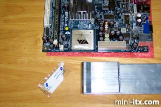
To prepare for assembly, remove the Heatlane heatpipe from the case by removing the four screws securing the two brackets and set all parts aside. Now we'll move on to the Via EPIA M motherboard.
The first step is to remove the heatsink and fan combo from your EPIA M. This is a delicate, sometimes frustrating task. You need to be very careful not only of static electricity but also of physically damaging the board. Needless to say, if you choose to do this to your board, you do so at your own risk. Remove the fan from the CPU Heatsink by removing the two black screws. Then, uncerimoniously toss the fan into the garbage.
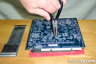
Now turn the board over and find the ends of the plastic pins that hold the CPU heatsink down. You need to compress the ends of those pins so that they can be pushed back up through the motherboard. Here I am trying to compress the pin ends.
Note that in this picture I'm actually trying to compress the wrong pin (but couldn't be bothered to retake the picture). The CPU heatsink pins are more toward the edge of the board. So be careful and make sure you are squeezing the correct ones. You also need to be careful that any tools you use do not scratch the surface of the motherboard and that any stress you apply not bend the board.
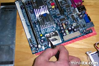
Once I got the (correct) pins back through the motherboard, I had to pop the CPU heatsink off of the CPU. It was actually rather attached so I had to apply a little persuasion with a flat-blade screwdriver. I did this very carefully, and I'm sure I'll get email about how risky it is to use such a tool. Just be extra extra careful at this step. Here is the motherboard with the CPU heatsink removed. Notice all the thermal compound still stuck to the CPU.
In order to remove the existing compound from the CPU I used a sharp hobby knife, as shown below. That worked for most of it and then some good old fashioned elbow grease to get the rest off. Remember to pay attention to the warnings above so as not to damage any components.
Then I applied some of the new compound supplied with the case to the CPU and smeared it around. Rather than use a high-performance thermal compound, I wanted to use the compound that was supplied with the case. I thought this would give a more acurate view of what most customers will experience. Note that I am not an overclocker or any kind of heatsink expert. So take my advice about the compound accordingly. Once the compound is applied to the CPU, it is time to put on the Heatlane heatpipe.
Slide the folded part of the heat pipe over the CPU. Don't worry about the heatpipe coming into contact with the bottom of the motherboard. Once everything is installed correctly it will be pulled away from the motherboard on to the e-Otonashi case.
Next comes the tricky part. You need to install the original CPU heatsink on top of the heatpipe and secure it the motherboard with parts supplied with the case.
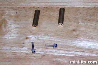
Use these long screws, washers, and long nuts to secure the old CPU heatsink to the top of the heatpipe (over the CPU). It may actually be easier to push the screws with their washers through the bottom of the motherboard before sliding the heatpipe over the CPU. Then secure the heatsink with the long nuts. Holding the heatsink on top of the heatpipe with one hand, and holding one of the screws with the other hand, simply tighten the long nut with your third hand. You get the idea.
It's actually not too difficult, just requires a little concentration.
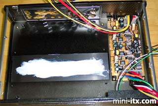
Before installing the motherboard assembly into the e-Otonashi case, I smeared the remaining thermal compound on to the bottom of the case where it was to contact the heatpipe. This was not indicated in the instructions but it seemed like a good idea.
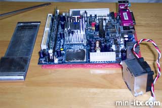
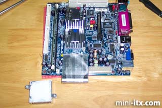
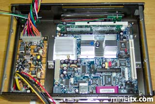
Next, insert the EPIA M back panel plate into the back of the case and then place the motherboard into the case. Secure it with the four small brass colored screws provided. Lastly, secure the heatpipe back onto the case with the screws and brackets you removed earlier. The complete assembly should look something like this:
Last steps for assembly are to connect all the wires to the motherboard. Unfortunately, none of the wires are labelled so you have to deduce which ones are what and consult your motherboard manual for the front panel connector layout. There are two pairs of wires on the left (when looking at the above picture). One pair is green and black and the other is white and black. On my system, the green was the power switch and the white was the reset switch.
There are also two pairs of wires on the right. A green and black pair (which should be the power LED) and a red and black pair (which should be the IDE activity LED). Lastly you need to connect the power cable from the power supply and you are all set (for diskless operation anyway, which is what I am interested in).
Another point I would like to make at this time is that unlike the earlier Morex 55W PSU (now increased to 60W), this one appears to have plenty of "umph" to power the Via EPIA M on-board LAN. Thus I didn't have to do any hardware tweaking to ensure reliable booting, which was nice.
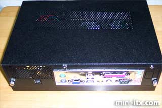
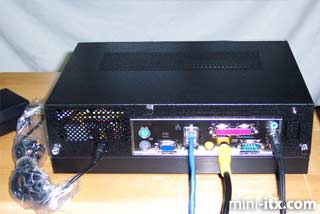
Once all the wires have been connected you can close up the box. Here are some pictures of the assembled unit.
Since I run the system diskless and typically hook it up to a TV, I need only minimal connections to test it; power, network, sound and video is all it takes to get this system up and running using MiniMyth.
Next: Performance -->
|