C64x Retro Keyboard Chassis 'Infinity' System Builders Kit (requires RAM, Storage, C64x Chassis)
| C64x Infinity Builders Kit (requires RAM, Storage, C64x Chassis) | |
| £660.00 inc. VAT | |
| IN STOCK (Checked 07:16) |
If you already have a C64x or just want to build your own Infinity System then we have all the parts you need in one single product code. It is also possible to purchase a subset of these parts if you already have some of them, by adding parts to the basket individually from the links below. If you want us to build and test everything for you, then we can do that for you.
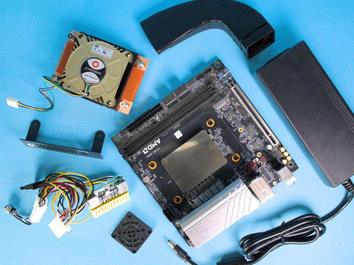
The Builders Kit for C64x Infinity System consists of:
- Phoenix-ITX 7940HS WiFi Motherboard
- Dynatron A18 Cooler
- 3D Printed Fan Duct or print one yourself from our STL file
- picoPSU-150-XT power supply
- C64x DC-In Side Panel to connect the picoPSU
- 150W AC Adapter
- 40mm fan shield, which mounts in front of the duct (nicer than the one provided with the C64x)
- Localised power cable whenever possible (UK, EU, US, AU and some others available)
For a full system you will additionally require (all linked underneath the photos in the 'Parts compatible with' section):
- C64x Retro Keyboard Chassis
- DDR5 DIMM(s) for the Phoenix-ITX motherboard
- M.2 Drive for your OS
You may also optionally require:
- Second M.2 Drive
- 2.5in HDD Tray/DVD Blanking Panel if your C64x did not come with one (pre-2025 versions)
- 2.5in SATA drive or 3.5in SATA drive
Build Instructions for C64x Infinity System
We will update these instructions as we go, and add some build photographs for key points. Build level is easy to moderate. The HDD Tray / DVD Blanking Panels can be a little tricky. Fitting a 3.5in drive requires a case modification, though not many people will need to do this.
- If you have a second M.2 drive, fit this to the underside of your motherboard (in our system builds we raise the back edge of the board slightly using spacers to give more room)
- Remove the plastic fittings either side of the AM5 socket on the board.
- Attach the Dynatron A18 cooler. Point the fan towards the PCIe slot and M.2 drive. Coil up the cable and connect it to the CPU_FAN header next to the 8pin socket.
- Fit the primary M.2 drive into the socket on the top of the board.
- Fit the memory. If you have one stick, put it in the slot nearest the cooler.
- Fit the picoPSU-150-XT into the 24pin ATX socket. Connect the 4pin connector into one side of the 8pin connector (it will only fit into one side).
- Open your C64x Chassis and fit the IO shield. Pop up the LAN port cover on the shield.
- Fit the motherboard and screw in all 4 corners. Ensure you have access to all the ports and refit if necessary.
- Remove the USB Side Panel from your C64x. Keep the screws. Screw in the DC connector of the picoPSU into the DC-In Side Panel. Fit the panel, looping the cable underneath the middle mounting stem to keep it in place.
- Fit the fan duct into the rear port of the C64x case, looping over the M.2 and PCIe slot and connecting to the A18. Use a small piece of tape to seal the top if necessary.
- Fit the narrow 40mm fan shield to the remaining space of the rear port.
- If you are fitting a 3.5in drive, unscrew the 'U' shaped metal tray and remove the metal standoffs with a rotary tool or strong pliers. Screw your 3.5in drive into the holes from below (this is quite tricky but is possible). Connect power from the picoPSU and a SATA data cable to the motherboard.
- 2.5in drives require some ingenuity as the fan duct obstructs the Mini SATA connector on the 2.5in Drive Tray / DVD Blanking Panel and also the standard mounting position on the 'U' shaped tray. The easiest way to mount a 2.5in drive is probably to use sticky pads and cable ties directly on the 'U' shaped metal tray. Connect power from the picoPSU and a SATA data cable to the motherboard.
- Fit the 2.5in Drive Tray / DVD Blanking Panel: Remove the thin plastic first, then carefully attach the front panel. Using the small black screws with washers supplied with your C64, start with the hole on the long side closest to the front panel, and then continue anti-clockwise. There is a danger of threading the thin metal of the tray if over-tightened. Gently push the tray down to align holes (use a light to check if necessary).
- Connect the LED and power switch of the top half of the case to the front panel board FPANEL header on the motherboard. This is on the edge of the board, just to the left of the 4x SATA connectors and has FPANEL printed next to it in small text.
- As you look at the FPANEL connector with the edge of the board closest to you, the top row will be from the left POWER LED +, POWER LED -, POWER SWITCH +-. The bottom row of 5 pins are unused.
- Connect the USB of the keyboard to the USB 2.0 pins on the motherboard.
- Loop these cables and cable-tie if possible.
- Close the case starting with the rear first and check everything is aligned correctly.
- Connect the 150W AC Adapter into the side panel of your C64x
- Connect your HDMI or DisplayPort monitor, and a mouse to one of the USB connections on the rear
- Power up and test your C64x. Do not be disheartened if something doesn't work immediately. Build gremlins are real but are usually thwarted. If we find customers are having common issues we will put them onto this page.
- Once you are happy everything is working, power off, flip over your C64x onto a towel to protect the keyboard, and carefully close up the case with the 6 self-tapping screws. Clamp the case shut with one hand as your screw in to ensure an aligned fit. Do NOT over-tighten these screws as the heads can shear off!