
Posted on July 2, 2004
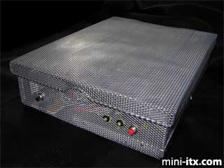
I have long been in awe of the beautiful and creative designs that people have created for the mini-itx form factor. Unfortunately I am a destructive force when paired with a tablesaw or dremel drill. So I searched around for projects that wouldn't require powertools and come up with the Mini-Mesh Box, which required nothing more destructive than a pair of wire cutters and a bottle of glue.
|
The resulting system is cool and quiet (no problems with venting!), and is currently acting as a PVR for my TV room.
Parts List
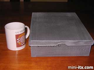
The main ingredient for my project was a mesh wire box with a hinged cover that I found at the local stationery store. It is designed to hold a ream of paper, and is roughly 9X12x2 inches in size.
Other parts that went into this project came from local computer, electronics, and hardware stores:
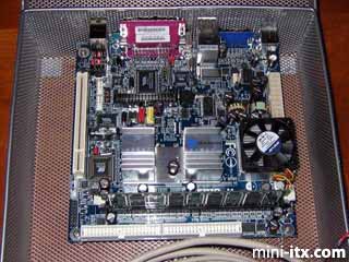
• Nehemiah EPIA M 10000 motherboard
• PW-80 80 watt PSU of the type that mounts directly on the board, plus the external 12V brick
• 256 Mb stick of PC2100 DDR RAM
• A 20 Gb IBM Travelstar 2.5 inch hard disk, and a slimline DVD/CD-RW, both salvaged from a dead laptop.
• 3.5" to 2.5" IDE adaptors for the hard disk and DVD/CD-RW
• Pushbutton switches
• 1/4" hexagonal standoffs
• Assorted LEDs and mounting retainer rings
• Crimp-style connector housings and ribbon cable
• Components for a serial port-based infrafred detector as described here
• A quieter 40 mm fan to replace the one that comes with the M10000
• A translucent vinyl report cover
• Miscellaneous screws and washers
Mounting the Motherboard
|
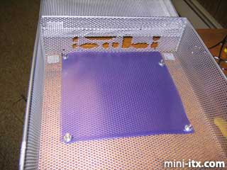
An issue with the mesh box is that the bottom is flexible, allowing it to bow upward and short out the motherboard. To avoid this eventuality, I cut two 17x17 cm sheets of translucent vinyl from a plastic report cover. During the preparation of the mesh box I used one of these as a template for cutting holes for the mounting screws. Later the two plastic sheets became electrical insulators between the motherboard and the box.
Using the template as my guide, I snipped two small holes in the mesh box underneath the mounting holes in the motherboard. I then screwed the standoffs in from below. The image above shows how the standoffs mount.
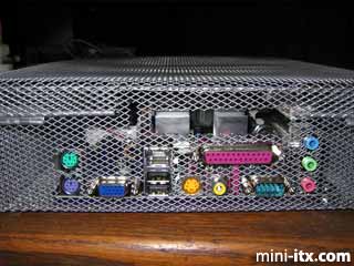
Now came the most time-consuming part of the project, cutting the holes for the backpanel ports. I used the metal backplate provided by VIA to trace the port pattern onto another piece vinyl, and taped the vinyl to the mesh. Then I started work with my wire cutters.
About an hour later, surrounded on all sides by tiny sharp pieces of waste metal, I placed the motherboard into the box, and behold, it fit!
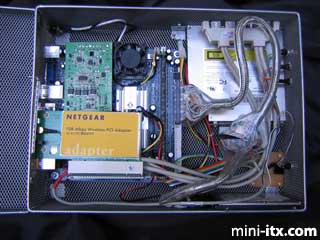
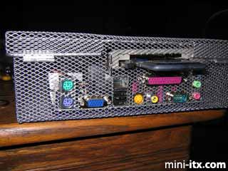
After mounting the board, I discovered that there remained just enough room to allow placing a PCI card using a riser board. However, when closed, the back rim of the mesh box would interfere with any ports protruding from the card. A few swift strokes of the hacksaw solved this problem without seeming to affect the structural integrity of the box or its lid.
If you look closely, you can see a small slot cut in the mesh just a bit to the left of the main opening for the PCI card. This slot accomodates the protruding lip of the PCI card's rear metal plate. The slot supports the lid nicely, preventing the card from wiggling around. The photograph below shows how the PCI slot looks when occupied by a CardBus bridge and a wireless card. I have since replaced the cardbus card with a PCI-based wireless card.
|
 |
 |
 |
Quick Links
Mailing Lists:
Mini-ITX Store
Projects:
Show Random
Accordion-ITX
Aircraft Carrier
Ambulator 1
AMD Case
Ammo Box
Ammo Tux
AmmoLAN
amPC
Animal SNES
Atari 800 ITX
Attache Server
Aunt Hagar's Mini-ITX
Bantam PC
BBC ITX B
Bender PC
Biscuit Tin PC
Blue Plate
BlueBox
BMW PC
Borg Appliance
Briefcase PC
Bubbacomp
C1541 Disk Drive
C64 @ 933MHz
CardboardCube
CAUV 2008
CBM ITX-64
Coelacanth-PC
Cool Cube
Deco Box
Devilcat
DOS Head Unit
Dreamcast PC
E.T.PC
Eden VAX
EdenStation IPX
Encyclomedia
Falcon-ITX
Florian
Frame
FS-RouterSwitch
G4 Cube PC
GasCan PC
Gingerbread
Gramaphone-ITX-HD
GTA-PC
Guitar PC
Guitar Workstation
Gumball PC
Hirschmann
HTPC
HTPC2
Humidor 64
Humidor CL
Humidor II
Humidor M
Humidor PC
Humidor V
I.C.E. Unit
i64XBOX
i-EPIA
iGrill
ITX Helmet
ITX TV
ITX-Laptop
Jeannie
Jukebox ITX
KiSA 444
K'nex ITX
Leela PC
Lego 0933 PC
Legobox
Log Cabin PC
Lunchbox PC
Mac-ITX
Manga Doll
Mantle Radio
Mediabox
Mega-ITX
Micro TV
Mini Falcon
Mini Mesh Box
Mini-Cluster
Mobile-BlackBox
Moo Cow Moo
Mr OMNI
NAS4Free
NESPC
OpenELEC
Osh Kosh
Pet ITX
Pictureframe PC
Playstation 2 PC
Playstation PC
Project NFF
PSU PC
Quiet Cubid
R2D2PC
Racing The Light
RadioSphere
Restomod TV
Robotica 2003
Rundfunker
SaturnPC
S-CUBE
SEGA-ITX
SpaceCase
SpacePanel
Spartan Bluebird
Spider Case
Supra-Server
Teddybear
Telefunken 2003
TERA-ITX
The Clock
ToAsTOr
Tortoise Beetle
Tux Server
Underwood No.5
Waffle Iron PC
Windows XP Box
Wraith SE/30
XBMC-ION