
or "Roll-Your-Own" Network Attached Storage Device
Posted on October 4, 2003
Altering and Mounting the Power Supply
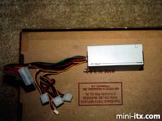
As you can see, the power supply has a pretty average 18 inches of wire between the P/S and the ATX connector. That is way too much to fit inside the Snap Server case so it needs to be shortened. The cables that supply power for devices also need to be altered to avoid excess cabling
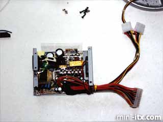
Altering this power supply takes a 40W soldering iron, lots of solder, and tons of patience. Due to the way the P/S is assembled, you cannot remove the board completely from the unit. The connector the power cord goes in is in the upper left of the image and is glued to several of the larger capacitors. Once you remove the screws from both the fan at the front of the P/S and the circuit board, you can bend back the rear of the P/S to get access to the solder points. I removed 10 inches of length from the ATX power cable.
In the front of the Snap Server case there are two round posts that are quickly removed with a Dremel. The squared posts behind them are used the attach the power supply support bracket to the case. Note the flange on the left; this has holes that will be used to hold the case closed.
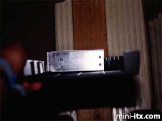
The power supply is attached to the mounting bracket with 1-1/2 inch 6-32 screws and 1-1/8 inch spacers. This allows enough room for a right-angle shielded power cable.
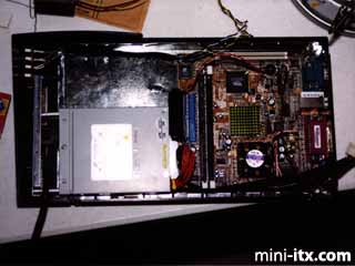
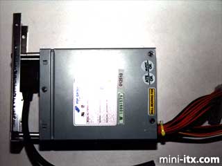
The P/S and bracket are secured to the front of the case and plugged into the motherboard for a test. It works perfectly.
The black/white and black/yellow wires at the top of the photo are for the power and reset switches, respectively.
 |
 |
 |
Quick Links
Mailing Lists:
Mini-ITX Store
Projects:
Show Random
Accordion-ITX
Aircraft Carrier
Ambulator 1
AMD Case
Ammo Box
Ammo Tux
AmmoLAN
amPC
Animal SNES
Atari 800 ITX
Attache Server
Aunt Hagar's Mini-ITX
Bantam PC
BBC ITX B
Bender PC
Biscuit Tin PC
Blue Plate
BlueBox
BMW PC
Borg Appliance
Briefcase PC
Bubbacomp
C1541 Disk Drive
C64 @ 933MHz
CardboardCube
CAUV 2008
CBM ITX-64
Coelacanth-PC
Cool Cube
Deco Box
Devilcat
DOS Head Unit
Dreamcast PC
E.T.PC
Eden VAX
EdenStation IPX
Encyclomedia
Falcon-ITX
Florian
Frame
FS-RouterSwitch
G4 Cube PC
GasCan PC
Gingerbread
Gramaphone-ITX-HD
GTA-PC
Guitar PC
Guitar Workstation
Gumball PC
Hirschmann
HTPC
HTPC2
Humidor 64
Humidor CL
Humidor II
Humidor M
Humidor PC
Humidor V
I.C.E. Unit
i64XBOX
i-EPIA
iGrill
ITX Helmet
ITX TV
ITX-Laptop
Jeannie
Jukebox ITX
KiSA 444
K'nex ITX
Leela PC
Lego 0933 PC
Legobox
Log Cabin PC
Lunchbox PC
Mac-ITX
Manga Doll
Mantle Radio
Mediabox
Mega-ITX
Micro TV
Mini Falcon
Mini Mesh Box
Mini-Cluster
Mobile-BlackBox
Moo Cow Moo
Mr OMNI
NAS4Free
NESPC
OpenELEC
Osh Kosh
Pet ITX
Pictureframe PC
Playstation 2 PC
Playstation PC
Project NFF
PSU PC
Quiet Cubid
R2D2PC
Racing The Light
RadioSphere
Restomod TV
Robotica 2003
Rundfunker
SaturnPC
S-CUBE
SEGA-ITX
SpaceCase
SpacePanel
Spartan Bluebird
Spider Case
Supra-Server
Teddybear
Telefunken 2003
TERA-ITX
The Clock
ToAsTOr
Tortoise Beetle
Tux Server
Underwood No.5
Waffle Iron PC
Windows XP Box
Wraith SE/30
XBMC-ION