
Posted on January 15, 2005
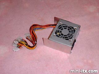
With the power supply attached to the mounting bracket, I made a test-fit in the case opening. After aligning the power supply assembly, I made measurements for cutting out side-tabs to mount the bracket to the case, and a hole in the "Z" fold at the back of the bracket for the assembly rod (the rod that ties the machine together from top to bottom) to fit through.
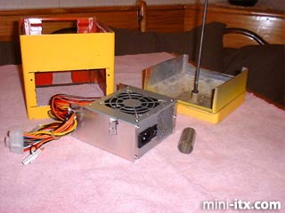
This photo displays the side-tab cutouts on the mounting bracket and the holes in the case where it will be bolted. The tube is a piece of tin cut to length and rolled into shape. It will fit over the assembly rod base to provide support for the power supply assembly.
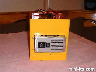
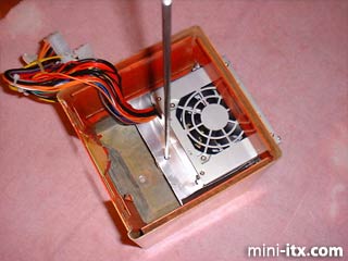
Rear view of the case after attaching the power supply assembly.
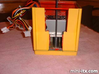
Front view of the case after attaching the power supply assembly. You can see how the tube is providing support for the power supply assembly. If you look closely, you can see the "Z" fold in the bottom of the bracket, just above the support tube
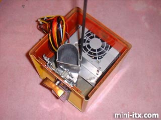
Top view of the case after attaching the power supply assembly. There is just enough room in the front of the case for the coin mechanism and drop tube. More on that later...
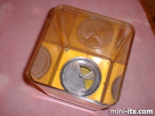
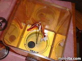
Top view of the "Globe" and its base. This is where the power needs to get to.
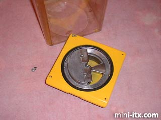
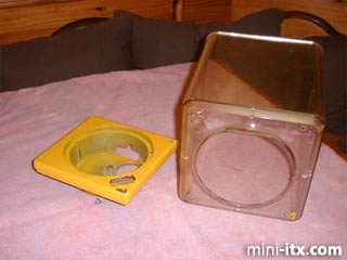
I removed the globe from its base and measured for a cutout based upon the size of the largest power connector, the one for the motherboard.
I used my Dremel to make the cutouts for the power cables.
The coin mechanism and the drop tube and cover are installed before the Globe and base go on.
Next, the power cables are fed through the cutout.
 |
 |
 |
Quick Links
Mailing Lists:
Mini-ITX Store
Projects:
Show Random
Accordion-ITX
Aircraft Carrier
Ambulator 1
AMD Case
Ammo Box
Ammo Tux
AmmoLAN
amPC
Animal SNES
Atari 800 ITX
Attache Server
Aunt Hagar's Mini-ITX
Bantam PC
BBC ITX B
Bender PC
Biscuit Tin PC
Blue Plate
BlueBox
BMW PC
Borg Appliance
Briefcase PC
Bubbacomp
C1541 Disk Drive
C64 @ 933MHz
CardboardCube
CAUV 2008
CBM ITX-64
Coelacanth-PC
Cool Cube
Deco Box
Devilcat
DOS Head Unit
Dreamcast PC
E.T.PC
Eden VAX
EdenStation IPX
Encyclomedia
Falcon-ITX
Florian
Frame
FS-RouterSwitch
G4 Cube PC
GasCan PC
Gingerbread
Gramaphone-ITX-HD
GTA-PC
Guitar PC
Guitar Workstation
Gumball PC
Hirschmann
HTPC
HTPC2
Humidor 64
Humidor CL
Humidor II
Humidor M
Humidor PC
Humidor V
I.C.E. Unit
i64XBOX
i-EPIA
iGrill
ITX Helmet
ITX TV
ITX-Laptop
Jeannie
Jukebox ITX
KiSA 444
K'nex ITX
Leela PC
Lego 0933 PC
Legobox
Log Cabin PC
Lunchbox PC
Mac-ITX
Manga Doll
Mantle Radio
Mediabox
Mega-ITX
Micro TV
Mini Falcon
Mini Mesh Box
Mini-Cluster
Mobile-BlackBox
Moo Cow Moo
Mr OMNI
NAS4Free
NESPC
OpenELEC
Osh Kosh
Pet ITX
Pictureframe PC
Playstation 2 PC
Playstation PC
Project NFF
PSU PC
Quiet Cubid
R2D2PC
Racing The Light
RadioSphere
Restomod TV
Robotica 2003
Rundfunker
SaturnPC
S-CUBE
SEGA-ITX
SpaceCase
SpacePanel
Spartan Bluebird
Spider Case
Supra-Server
Teddybear
Telefunken 2003
TERA-ITX
The Clock
ToAsTOr
Tortoise Beetle
Tux Server
Underwood No.5
Waffle Iron PC
Windows XP Box
Wraith SE/30
XBMC-ION