
Posted on November 21, 2002
|
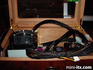
Tail end of PSU brick being lifted up to clear cables then....
|
The 95W PSU comes up and out then rests on the table without anything being disconnected! The PSU has two 4-pin connectors and one floppy-style connector.
|
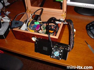
Unfinished inside interface opening. The height of the PSU opening is 3/4" taller than it needs to be. This creates a "slot" underneath the electrical box, which passes cables and air. The motherboard is mounted sideways so that the cables have to make an immediate right turn to exit out under the PSU.
|
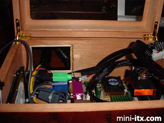
This is what I call the money shot. It shows the cabling and routing in detail. The extra long wireless receiver cable was wound up and stowed. Hard drive to the left. Tip of LED light at forefront of picture. ThermalTake memory cooler to the right. I especially like the mesh fit over the USB light. I didn't pull it all the way past the bulb. Instead I left excess mesh around the light, which creates a more subtle effect.
|
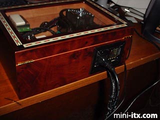
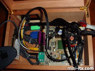
Back door shot. This has been my most challenging design idea. A single rectangular cut in the back of a wooden box, such as the size of this 75ct humidor, solved the problem. It doesn't matter if the EPIA-M has a different connector layout. It also allows me to pursue the umbilical style of cable system management.
 |
 |
 |
Quick Links
Mailing Lists:
Mini-ITX Store
Projects:
Show Random
Accordion-ITX
Aircraft Carrier
Ambulator 1
AMD Case
Ammo Box
Ammo Tux
AmmoLAN
amPC
Animal SNES
Atari 800 ITX
Attache Server
Aunt Hagar's Mini-ITX
Bantam PC
BBC ITX B
Bender PC
Biscuit Tin PC
Blue Plate
BlueBox
BMW PC
Borg Appliance
Briefcase PC
Bubbacomp
C1541 Disk Drive
C64 @ 933MHz
CardboardCube
CAUV 2008
CBM ITX-64
Coelacanth-PC
Cool Cube
Deco Box
Devilcat
DOS Head Unit
Dreamcast PC
E.T.PC
Eden VAX
EdenStation IPX
Encyclomedia
Falcon-ITX
Florian
Frame
FS-RouterSwitch
G4 Cube PC
GasCan PC
Gingerbread
Gramaphone-ITX-HD
GTA-PC
Guitar PC
Guitar Workstation
Gumball PC
Hirschmann
HTPC
HTPC2
Humidor 64
Humidor CL
Humidor II
Humidor M
Humidor PC
Humidor V
I.C.E. Unit
i64XBOX
i-EPIA
iGrill
ITX Helmet
ITX TV
ITX-Laptop
Jeannie
Jukebox ITX
KiSA 444
K'nex ITX
Leela PC
Lego 0933 PC
Legobox
Log Cabin PC
Lunchbox PC
Mac-ITX
Manga Doll
Mantle Radio
Mediabox
Mega-ITX
Micro TV
Mini Falcon
Mini Mesh Box
Mini-Cluster
Mobile-BlackBox
Moo Cow Moo
Mr OMNI
NAS4Free
NESPC
OpenELEC
Osh Kosh
Pet ITX
Pictureframe PC
Playstation 2 PC
Playstation PC
Project NFF
PSU PC
Quiet Cubid
R2D2PC
Racing The Light
RadioSphere
Restomod TV
Robotica 2003
Rundfunker
SaturnPC
S-CUBE
SEGA-ITX
SpaceCase
SpacePanel
Spartan Bluebird
Spider Case
Supra-Server
Teddybear
Telefunken 2003
TERA-ITX
The Clock
ToAsTOr
Tortoise Beetle
Tux Server
Underwood No.5
Waffle Iron PC
Windows XP Box
Wraith SE/30
XBMC-ION