
or "Roll-Your-Own" Network Attached Storage Device
Posted on October 4, 2003
Parts List
• Quantum Snap Server 2000 Case
• VIA EPIA 800 Mini-ITX Motherboard (800Mhz)
• 512MB PC133 DIMM
• Flex ATX-090 PSU
• 10.05GB IBM Travelstar 4,200RPM Laptop Hard Drive x 7
• SIIG Ultra ATA/133 Low-Profile
IDE Controller
• Sony CRX700E CD-R/RW Drive
• Laptop CD-ROM to IDE Adapter
• 40- to 44-pin Laptop Hard drive Converter x 4
• 2mm 44-pin IDE Ribbon Cable(in
feet) x 5
• 44 Pin Male Plug Type IDC Connector x 3
• 44 Pin Female Socket Type IDC Connector x 6
• 60mm 3-pin Fan for Hard Drive Array
• Right-Angle
PCI Extender
• LEDs, Screws, Aluminum Plates, Reset & Power Buttons, Miscellaneous
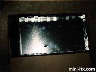
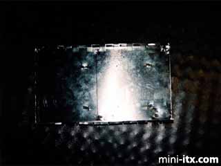
The first step was taking the Faraday shield out of the "Snap Server" labelled side of the case to use as the hardware mounting tray. In order to maximize usable space in the case, I used a Dremel to cut away the vent grill on the front of the Faraday shield / tray.
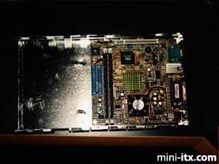
A quick test fit of the VIA motherboard in the tray to get an idea of MB placement. Some of the Faraday cage contacts along the top of the tray had to be folded down to provide clearance for the SIIG IDE controller.
Adding the I/O shield and four 1/4-inch, hexagonal standoffs to the motherboard allowed me to mark the cut out lines for the rear of the hardware tray.
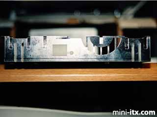
A quick run of the Dremel along the guidelines and a bit of filing gives a nice, smooth edge.
Another fitting of the motherboard to mark the forward edge of the motherboard in the tray and where the motherboard mounting holes will go. Then drill the holes and attach the standoffs.
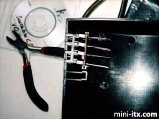
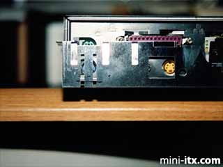
Using a small piece of a breadboard PCB, I added the LEDs for the System power, Network activity, Link, and Disk activity.
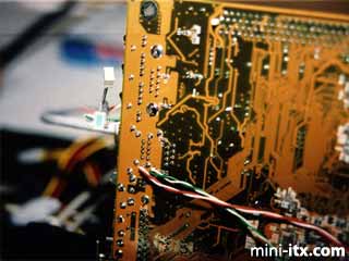
Since the Mini-ITX board doesn't have additional headers on it for the front panel lights (hint, hint to the engineers at VIA), I had to add my own. You have to be VERY careful when soldering wires to the appropriate spots on the motherboard. I recommend using a 15W soldering iron to prevent damaging components that are in proximity to the solder points. In this image you can see the lights on the left during a test.
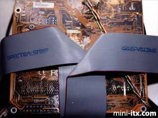
In order to avoid cluttering the inside of the case with cables and blocking air-flow, I routed the IDE cable for the CD-RW under the motherboard (the cable to the left). The cable going to the right was my original attempt to connect the hard drives for the OS.
At this point, the motherboard is ready for mounting on the hardware tray.
 |
 |
 |
Quick Links
Mailing Lists:
Mini-ITX Store
Projects:
Show Random
Accordion-ITX
Aircraft Carrier
Ambulator 1
AMD Case
Ammo Box
Ammo Tux
AmmoLAN
amPC
Animal SNES
Atari 800 ITX
Attache Server
Aunt Hagar's Mini-ITX
Bantam PC
BBC ITX B
Bender PC
Biscuit Tin PC
Blue Plate
BlueBox
BMW PC
Borg Appliance
Briefcase PC
Bubbacomp
C1541 Disk Drive
C64 @ 933MHz
CardboardCube
CAUV 2008
CBM ITX-64
Coelacanth-PC
Cool Cube
Deco Box
Devilcat
DOS Head Unit
Dreamcast PC
E.T.PC
Eden VAX
EdenStation IPX
Encyclomedia
Falcon-ITX
Florian
Frame
FS-RouterSwitch
G4 Cube PC
GasCan PC
Gingerbread
Gramaphone-ITX-HD
GTA-PC
Guitar PC
Guitar Workstation
Gumball PC
Hirschmann
HTPC
HTPC2
Humidor 64
Humidor CL
Humidor II
Humidor M
Humidor PC
Humidor V
I.C.E. Unit
i64XBOX
i-EPIA
iGrill
ITX Helmet
ITX TV
ITX-Laptop
Jeannie
Jukebox ITX
KiSA 444
K'nex ITX
Leela PC
Lego 0933 PC
Legobox
Log Cabin PC
Lunchbox PC
Mac-ITX
Manga Doll
Mantle Radio
Mediabox
Mega-ITX
Micro TV
Mini Falcon
Mini Mesh Box
Mini-Cluster
Mobile-BlackBox
Moo Cow Moo
Mr OMNI
NAS4Free
NESPC
OpenELEC
Osh Kosh
Pet ITX
Pictureframe PC
Playstation 2 PC
Playstation PC
Project NFF
PSU PC
Quiet Cubid
R2D2PC
Racing The Light
RadioSphere
Restomod TV
Robotica 2003
Rundfunker
SaturnPC
S-CUBE
SEGA-ITX
SpaceCase
SpacePanel
Spartan Bluebird
Spider Case
Supra-Server
Teddybear
Telefunken 2003
TERA-ITX
The Clock
ToAsTOr
Tortoise Beetle
Tux Server
Underwood No.5
Waffle Iron PC
Windows XP Box
Wraith SE/30
XBMC-ION