
or "Roll-Your-Own" Network Attached Storage Device
Posted on October 4, 2003
Building the Disk Array (2)
I stacked the 6 hard drives together, each separated by a stack of 3 index cards to determine where to drill the holes for the drives. This spacing is necessary to prevent the air intake holes from being blocked by the drive above. The bottom-most hard drive in the stack is not flush with the bottom of the bracket. 5mm of space is necessary to allow for the screws that will hold the drive bracket in the Snap Server case. Don't forget to add the jumpers to every other hard drive to make them slaves!
Mark the position for each hole, drill, mount the hard drives and, 24 screws later (Hot swap? What's that?), you have a drive array.
Using the holes already in the perpendicular flanges and a few cable ties, I attached a 60mm fan for cooling the hard drives. The fan also provides a good air flow in the case.
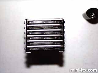
Next, cut two 18-inch lengths of 2mm 44-conductor ribbon cable and crimp a 44-pin female connector to one end of each cable (watch your pin 1 placement). Then connect one cable to the bottom-most hard drive, skip the next one, and connect the second cable to the third drive from the bottom. Now mark on each cable where the second connector on each should be attached. Remove the cables and crimp on the second 44-pin female IDE connector.
Test fit the hard drive stack into the Snap Server case and plug the controller/PCI riser combo into the PCI slot on the motherboard. This allows us to measure the cable length needed to reach the 44-pin to 40-pin adapters on the SIIG controller. Cut the 44-conductor ribbon cable to fit plus an extra 1/2-inch for slack.
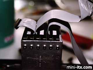
Cut a 6-inch piece of the 44-conductor ribbon cable and repeat the crimping on procedure for the female connectors as above EXCEPT route the cable downward (see picture).
Disconnect all three cables from the hard drives. Take the connector-less end of each cable an use a pair of wire cutters to separate the conductors in the ribbon cables in pairs (1&2, 3&4, etc). The last step is to attach the 44-pin male connectors to the ribbon cable by flipping each pair of conductors that you just separated. What you are doing is creating a custom length, I-Opener IDE cable
Reconnect the cables to the hard drives and to the controller. Fold the cable for the top two drives under itself then over itself to form a delta shape. This will allow the 44-pin male connector on the cable fit into the 44-pin to 40-pin adapter properly for the seondary motherboard IDE channel.
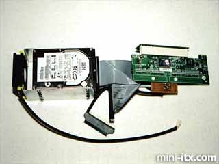
Now, we have our completed drive array!
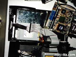
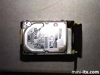
The seventh drive is attached as the slave device on the motherboard's primary IDE channel. The primary on the IDE channel is the CD-RW drive (see below). Unfortunately, the laptop-to-40-pin adapter is hard-wired for master.
There is just enough room between the top of the power supply and the Snap Server case to fit the hard drive. First, we create a 40-pin IDE cable by crimping on two 40-pin female connectors. Then we separate each conductor in the ribbon cable between the two connectors and for 4-inches above the center connector. A fold to route the cable under the motherboard and out the bottom of the case then plug the end connector into the primary IDE channel ends this step.
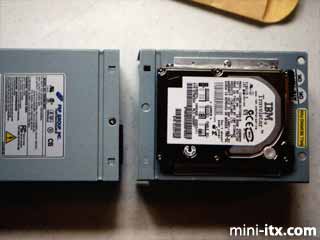
Fortunately, removing the top of the power supply is easy; all you have to do is remove the three screws on the top. The pieces cut from the 6-drive bracket are sized perfectly for mounting brackets for the seventh (boot) drive. Only two holes in the top of the power supply are necessary.
 |
 |
 |
Quick Links
Mailing Lists:
Mini-ITX Store
Projects:
Show Random
Accordion-ITX
Aircraft Carrier
Ambulator 1
AMD Case
Ammo Box
Ammo Tux
AmmoLAN
amPC
Animal SNES
Atari 800 ITX
Attache Server
Aunt Hagar's Mini-ITX
Bantam PC
BBC ITX B
Bender PC
Biscuit Tin PC
Blue Plate
BlueBox
BMW PC
Borg Appliance
Briefcase PC
Bubbacomp
C1541 Disk Drive
C64 @ 933MHz
CardboardCube
CAUV 2008
CBM ITX-64
Coelacanth-PC
Cool Cube
Deco Box
Devilcat
DOS Head Unit
Dreamcast PC
E.T.PC
Eden VAX
EdenStation IPX
Encyclomedia
Falcon-ITX
Florian
Frame
FS-RouterSwitch
G4 Cube PC
GasCan PC
Gingerbread
Gramaphone-ITX-HD
GTA-PC
Guitar PC
Guitar Workstation
Gumball PC
Hirschmann
HTPC
HTPC2
Humidor 64
Humidor CL
Humidor II
Humidor M
Humidor PC
Humidor V
I.C.E. Unit
i64XBOX
i-EPIA
iGrill
ITX Helmet
ITX TV
ITX-Laptop
Jeannie
Jukebox ITX
KiSA 444
K'nex ITX
Leela PC
Lego 0933 PC
Legobox
Log Cabin PC
Lunchbox PC
Mac-ITX
Manga Doll
Mantle Radio
Mediabox
Mega-ITX
Micro TV
Mini Falcon
Mini Mesh Box
Mini-Cluster
Mobile-BlackBox
Moo Cow Moo
Mr OMNI
NAS4Free
NESPC
OpenELEC
Osh Kosh
Pet ITX
Pictureframe PC
Playstation 2 PC
Playstation PC
Project NFF
PSU PC
Quiet Cubid
R2D2PC
Racing The Light
RadioSphere
Restomod TV
Robotica 2003
Rundfunker
SaturnPC
S-CUBE
SEGA-ITX
SpaceCase
SpacePanel
Spartan Bluebird
Spider Case
Supra-Server
Teddybear
Telefunken 2003
TERA-ITX
The Clock
ToAsTOr
Tortoise Beetle
Tux Server
Underwood No.5
Waffle Iron PC
Windows XP Box
Wraith SE/30
XBMC-ION